
|
Outline
This procedure eliminates or reduces the bow, twist, or warping of circuit boards.
|
|||||||||||||||||||||||||
|
Procedure
Evaluation
|
|||||||||||||||||||||||||
Images and Figures
Bow and Twist Repair
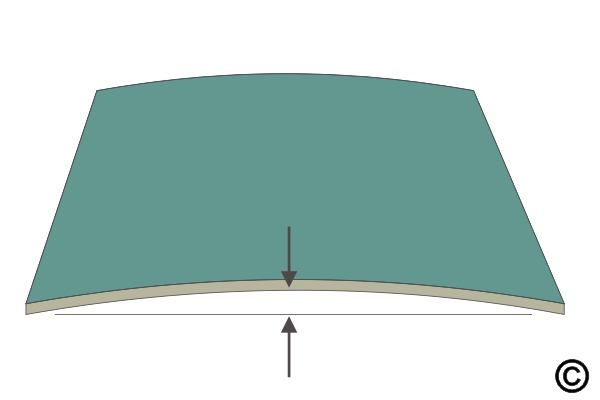
Figure 1. Check the deflection to determine if the rework is needed.
Figure 2. Place the restraint bars along the edges that require rework.
Figure 3. Place the circuit board, restraint bars, and base plate in the oven and bake for 1 hour at 125 degrees C - 257 degrees F.
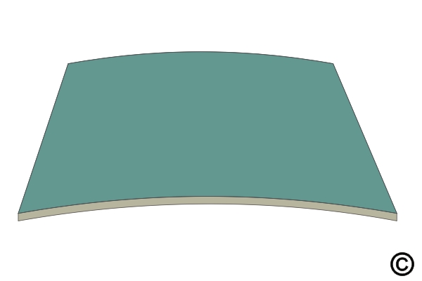
Figure 4. Remove from the oven and allow to cool to room temperature. Remove restraint bars. Check the edge deflection using a caliper or pin gauges.
|
|||||||||||||||||||||||||
3.2 Bow and Twist Repair
This procedure covering bow and twist repair on circuit board assemblies.
Minimum Skill Level: Intermediate
Conformance Level: High
REQUEST FOR QUOTE GUIDES INDEX

