Outline
This procedure covers reballing of BGA components.
Minimum Skill Level - Expert
Recommended for technicians with advanced soldering and component rework skills and extensive experience in most repair/rework procedures.
Conformance Level - High
This procedure most closely duplicates the physical characteristics of the original, and most probably complies with all the functional, environmental and serviceability factors.
Cleaner
General purpose cleaner for removing contamination.
Cleaning System
Batch or inline cleaning system for removing fluxes and contamination.
Microscope
Precision microscope with stand and lighting for work and inspection.
Oven
General purpose oven for drying, baking and curing epoxies.
Safety Glasses
Protect your eyes and your vision with proper safety glasses.
Solder Flux
Used to prepare solder surfaces and to prevent formation of oxides during soldering.
Solder Spheres
Solder balls or spheres for BGA component reballing and rework.
Wipes
Nonabrasive, low-linting wipes for cleanup.
Images and Figures
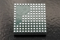
BGA component prior to reballing.
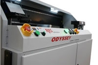
Figure 1. Robotic deball system for controlled removal of solder balls.
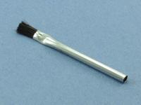
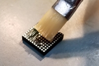
Figure 2. Apply tacky flux to flat BGA component pads using a brush.
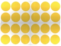
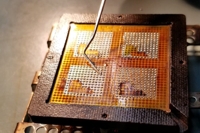
Figure 3. Place the BGA component(s) into a fixture and cover with the appropriate stencil.
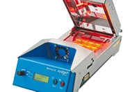
Figure 4. Mini reflow oven used for controlled reflow of solder balls.
Procedure - Touchless Ball Removal
This BGA component de-ball process dissolves and flushes away the existing solder balls, leaving a flat surface on each of the BGA component solder pads.
Ensure the BGA components to be processed meet the requirements for acceptable moisture levels.
Note: For information on baking and moisture level control see 2.5 Baking and Preheating.
If the BGA components are supplied on tape and reel, a matrix tray or custom holding fixture will be required.
Set up the robotic de-ball system with the proper process parameters, including solder immersion depth, dwell times, insertion and extraction speeds, solder temperature, and other settings.
Note: Refer to the component data sheet for guidelines regarding component peak temperatures specifications, and other process parameters.
Load the BGA components onto the fixture or matrix tray and place them into the robotic BGA deball system.
Activate the robotic machine process cycle.
Pick up a row of components from the matrix tray using a multi-head vacuum pickup.
Apply flux to the existing solder balls.
Remove the excess flux using an air knife.
Run the components through a programmed preheat stage to activate the flux.
Remove the unwanted solder balls using a dynamic solder wave.
Run the components through a filtered hot water rinse to remove the flux residues.
Dry the components using an air knife.
Return the de-balled BGA components to their original position in the matrix tray.
Visually inspect the BGA component appearance, cleanliness, and condition. Check the solder pads for flatness and inspect the body of the BGA component for abnormalities.
Procedure - Mini-Oven Attachment Method
Apply tacky flux to the flat BGA component pads using a Brush. Flux should be evenly applied across the entire BGA pad surface. Use minimal flux needed to fully cover the surface. Remove any excess flux. See Figure 2.
Place a quantity of the appropriate size Solder Spheres into the fixture and use a clean Cleaning Brush to distribute the Solder Spheres, so they fill all the open apertures in the BGA Component Stencil. Check to be sure all the apertures are filled with only one solder sphere. Tilt the fixture and pour the excess Solder Spheres into a collection container for reuse. See Figure 3.
Note: Avoid overloading the Solder Stencil with excess Solder Spheres as they may wedge under the stencil. This will make lifting the Stencil to remove any excess Solder Spheres difficult.
Place the component and fixture into the Mini BGA Reflow Oven. See Figure 4.
Turn the Mini BGA Reflow Oven on and select the proper profile. Note: If a profile has not been defined, a profile will need to be created.
Close the cover of the Mini BGA Reflow Oven and press the start button. The oven will go through the required preheat, reflow, and cooling cycles.
When the temperature has cooled below 100 ° C, use gloves and remove the reball fixture from the Mini BGA Reball Oven once. Allow the fixture and components to cool for one minute to ensure package thermal stability prior to removing the BGA component from the fixture.
Visually inspect the BGA components balls for proper alignment and appearance.
Clean the BGA components in an approved cleaning solution.
Inspect the body of the BGA component for abnormalities.