9.2.1 BGA Component Rework Profile Development, Standard Method
Outline
This process covers the development and criteria for establishing profiles for BGA removal and replacement.
Minimum Skill Level - Advanced
Recommended for technicians with soldering and component rework skills and exposure to most repair/rework procedures, but lacking extensive experience.
Conformance Level - High
This procedure most closely duplicates the physical characteristics of the original, and most probably complies with all the functional, environmental and serviceability factors.
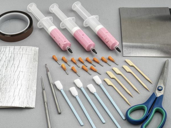
Kits and Systems
Heat Shield Kit
Kit includes tools and materials needed to protect heat sensitive area of a circuit board during rework.
Precision Tool Set
Nine precision-crafted tools for detailed circuit board work.
BGA Rework System
Hot air or infrared BGA component rework system.
Cleaner
General purpose cleaner for removing contamination.
Microscope
Precision microscope with stand and lighting for work and inspection.
Oven
General purpose oven for drying, baking and curing epoxies.
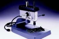
Precision Drill
Precision drill press for accuracy and controlled depth drilling.
Wipes
Nonabrasive, low-linting wipes for cleanup.
Heat Shield
During component rework, protection of nearby components is often mandatory to avoid collateral heat damage or inadvertent reflow. Collateral heat damage or unintended reflow of adjacent component solder connections can result in component damage, oxidation, de-wetting, pad damage, wicking, starved joints, and scorching. The rework technician must constantly be aware of the effect of heat on the target device or circuit, plus how it affects components near the target device on both sides of the assembly.
235-4010 Heat Shield Blanket
These are 5" x 7" sheets of fiberglass fabric, aluminum foil laminate with a pressure-sensitive adhesive backing. Heat Shield Blanket is designed to reflect 90% of the radiant heat energy. It will withstand continuous heat in the leaded and lead-free solder melt temperature range and short-term exposure at temperatures up to 1000°F/538°C. Heat Shield Blankets can be used in conjunction with Heat Shield Plates to create a more robust thermal shield with a more rigid structure.
235-4060 Heat Shield Plates
These are light gauge 5" x 7" aluminum sheets used primarily when simple heat deflection is required. Heat Shield Plates are easy to size, cut, form, and bond or tape into place using the high-temperature mask or high-temperature tape supplied in the kit. When using Heat Shield Plate material to deflect heat, leave a small space between the Heat Shield Plate and the protected component or area to avoid direct contact transfer of heat.
115-9010 Mask, High Temperature
This product is a high-temperature, quick cure, synthetic latex, peel-able solder mask supplied in syringes with dispensing needles. This mask can create free-form heat shielding or seal the edges of the Heat Shield Blanket or Heat Shield Plates. This mask cures at room temperature in 5 minutes. Once dried, it can be peeled off after use.
Images and Figures
Ball Grid Array Rework Station
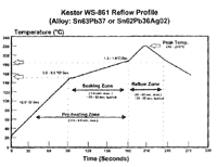
Figure 1: Flux manufacturers reflow profile.
Figure 2: Precision drill press.
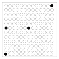
Figure 3: Thermocouple locations.
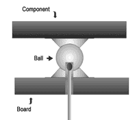
Figure 4: Ideal thermocouple placement.
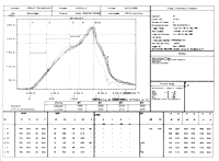
Figure 5: Temperature data using analysis software.
Caution - Operator Safety: A thorough review of the equipment manual and comprehensive training is mandatory. Daily maintenance is essential. Consult the equipment manual for more information.
Caution - Component Sensitivity: This method may subject the component to extreme temperatures. Evaluate the component's tolerance to heat prior to using this method. Plastic BGAs are especially sensitive to moisture absorption. Carefully evaluate pre-bake requirements.
Caution - Circuit Board Sensitivity: Circuit boards are made from a great variety of materials. When subjected to high temperatures, they are susceptible to the following types of damage:
1. Layer delamination.
2. Copper delamination, separation of pads, barrels of inner layers.
3. Burns and solder mask chipping.
4. Warp.
Each circuit board must be treated individually and scrutinized carefully for its reaction to heat. If a series of circuit boards are to be reworked, the first several should be handled with extreme care until a reliable procedure is established.
Note: This procedure references temperatures used when processing BGA components soldered using tin-lead solders. Temperature adjustments may be required when processing components soldered using higher temperature lead-free solders.
Procedure
General Instructions
Note: Your solder paste manufacturer will have a recommended time/temperature curve for these applications. It is recommended as guidance for profile development. (See Figure 1)
One fully assembled development board is required.
4 to 6 sample BGA components for development may be required.
A steady state operating temperature or threshold must be established prior to launching the reflow cycle. A consistent temperature starting point is necessary for repeatable results. Between 110 C and 140 C is recommended.
BGA Soldering Profile Instructions
Note: The BGA replacement profile may require more time and even more heat (usually not more than 20 seconds time) to not only reflow all joints but to properly evacuate flux gases and create uniform joints across the package.
Insert thermocouples into the holes. Ideally, the thermocouple is secured in place by the solder of the pad that the thermocouple is placed in. (See Figure 4) Otherwise, secure it in place with high-temperature tape and thermal adhesive. Additional thermocouples will also be placed on the top of the circuit board, about two inches from the site, and on the bottom side under the site. These thermocouples may be merely taped in place.
Select an appropriate nozzle and install it. Be mindful of the component height and clearance area around the component.
Secure the board in place with appropriate tooling, clamps, and pins. The board should be secure but allowed to move with thermal expansion. Antistatic solder wave fixtures may be used to prevent warp.
Connect the thermocouples (drilled locations) to a temperature recorder. Connect other monitoring thermocouples to handheld digital thermometers as required. The temperature recorder should present a graphic display as per Figure 5.
Select soldering process parameters from similar existing profiles. If none are available, contact the manufacturer of the rework station.
Note: It may be advisable to shut off all vacuum commands when developing a removal profile to prevent inadvertent component removal.
Note: Pre-bake the board to drive out accumulated moisture. The length of pre-bake will be affected by the board's environmental exposure. A pre-bake temperature of 75 C to 100 C is recommended.
Place a pre-baked board onto the fixture.
Establish a bottom side under the part threshold temperature from which to begin the reflow ramp. 140 C underneath the part should correspond to approximately 90 C at 2" from the nozzle on the board's top side. Choosing a starting point in this approximate temperature range will help to reduce localized warping during BGA ball reflow.
Run the process and monitor the temperature of the bottom and top of the board, next to and under the component.
Disconnect the thermocouples and download recorded data.
Analyze the data and optimize parameters for reliable rework as follows:
1. Maximum temperature at the solder ball/board pad interface should be 205 C.
2. Minimize temperature differential to less than 15 C for internal thermocouples measuring the various solder ball/board pad interface.
3. Time above 183 C should be between 30 and 60 seconds.
4. Temperature rise and fall should not exceed 3 C/ Sec ramp.
Make changes to process settings as applicable.
Run the process and return to step 13.
Examine the surface under the component for warp.
Note: Excessive localized warp may be reduced by increasing the pre-ramp temperature threshold. A convection oven can be used to decrease the thermally induced stress caused by the process. Even heating across the whole board may be required.
Develop Removal Process
Note: The component will typically release from its pads when two of the thermocouples measuring joint locations pass the 183 C mark. In order to reduce mask, part, or board damage due to excessive heat, the removal cycle is typically shorter than the replacement cycle. Reflow the joints just enough to effect removal.
Copy the parameters of the soldering profile to develop the removal profile.
Change process parameters as needed.
Connect the thermocouples (drilled locations) to the temperature recorder. Connect monitoring thermocouples to the handheld digital thermometers.
Run the process and monitor externally connected thermocouples.
Disconnect the thermocouples and download recorded data.
Analyze the data and optimize parameters for reliable rework as follows:
1. Maximum temperature at any location should be 210 C.
2. Minimize temperature differential to less than 15 C for internal thermocouples.
3. Time above 183 C should be between 30 - 60 seconds.
Adjust process parameters as needed.
Determine the time in the process when all ball locations reach 183 C. Note the bottom side monitoring thermocouple temperature.
Reconnect thermocouples.
Inject flux under the component.
Run the process and lift the nozzle three seconds after the reflow has been reached.
Remove the component using the vacuum tool.
Note: If software controls the vacuum, select the vacuum on command for all events. This will lift the component as soon as reflow temperatures have been reached.
If the component can not be removed, analyze the temperature data and adjust the parameters. Return to step 10.
Inspect the BGA footprint area for signs of unexpected overheating, solder mask, or pad damage.