Outline
This procedure covers the general guidelines for modifications that involve cutting and lifting component leads. Leads may be permanently cut or lifted due to engineering changes or reconnected if done for testing purposes.
Minimum Skill Level - Advanced
Recommended for technicians with soldering and component rework skills and exposure to most repair/rework procedures, but lacking extensive experience.
Conformance Level - Medium
This procedure may have some variance with the physical character of the original and most likely varies with some of the functional, environmental and serviceability factors.
Kits and Systems
Precision Tool Set
Nine precision-crafted tools for detailed circuit board work.
Tools and Materials
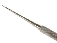
Probe
Sharp dental-style probe for manipulating small objects and removal of debris.
Additional Items and Supplies
Cleaner
General purpose cleaner for removing contamination.
Cutters and Pliers
Precision grade cutters and pliers.
Microscope
Precision microscope with stand and lighting for work and inspection.
Soldering Iron
Properly maintained soldering iron and properly sized soldering iron tips.
Wipes
Nonabrasive, low-linting wipes for cleanup.
Images and Figures
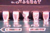
Figure 1: Component Lead Cutting
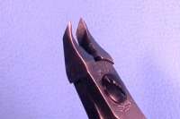
Figure 2: Specially designed cutters used to cut component leads.
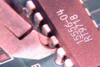
Figure 3: Place the cutter at the mid point in the lead and snip through to cut the lead.
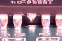
Figure 4: To ensure that the lead has been severed, the upper portion of the lead may be slightly lifted using a pick.
Figure 5: If needed, solder both halves of the severed lead together.
Figure 6: Place the cutter at the mid point in the lead and snip through to cut the lead.
Figure 7: To ensure that the lead has been severed, the upper portion of the lead may be slightly lifted using a pick.
Figure 8: If needed, solder both halves of the severed lead together.
Figure 9: Gently place a pick behind the component lead to be lifted. Apply a soldering iron tip to the foot of the component lead. Apply slight force with the pick to lift the lead as the soldering iron reflows the joint.
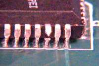
Figure 10: Visually inspect, or electrically test, to ensure that the lead has been lifted.
Figure 11: Gently place a pick behind the component lead to be lifted. Apply a soldering iron tip to the foot of the component lead. Apply slight force with the pick to lift the lead as the soldering iron reflows the joint.
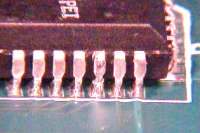
Figure 12: Visually inspect, or electrically test, to ensure that the lead has been lifted.
Note: Specially designed cutters are required when cutting component leads.
Procedure - Lead Cutting, Plated Through Hole Components
Select the component lead that needs to be cut and place the cutter in position. (See Figure 3) Place the cutter at the midpoint in the lead and snip through to cut the lead.
To ensure that the lead has been severed, the upper portion of the lead may be slightly lifted using a pick. Visually inspect or electrically test to ensure that the lead has been severed.
If the lead needs to be reconnected, gently push the upper portion of the severed lead down until it touches the lower portion of the severed lead.
Solder both halves of the severed lead together. (See Figure 5)
Note: The lower portion of the lead may move during soldering since it is not anchored in position.
If required, clean the flux residue and inspect.
Procedure - Lead Cutting, J Lead Components
Select the component lead that needs to be cut and place the cutter in position. (See Figure 6) Place the cutter at the midpoint in the lead and snip through to cut the lead.
To ensure that the lead has been severed, the upper portion of the lead may be slightly lifted using a pick. (See Figure 7) Visually inspect or electrically test to ensure that the lead has been severed.
If the lead needs to be reconnected, gently push the upper portion of the severed lead down until it touches the lower portion of the severed lead.
Solder both halves of the severed lead together. (See Figure 8)
Note: The lower portion of the lead may move during soldering since it is not anchored in position.
If required, clean the flux residue and inspect.
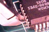
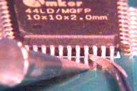
Procedure - Lead Lifting, Standard Gull Wing Components
Select the component lead that needs to be lifted. Apply a soldering iron and solder braid to remove the excess solder from the joint.
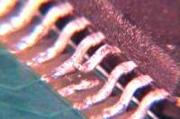
Gently place a pick behind the component lead to be lifted. Apply a soldering iron tip to the foot of the component lead. Apply slight force with the pick to lift the lead as the soldering iron reflows the joint. (See Figure 9)
Visually inspect or electrically test to ensure that the lead has been lifted. See (Figure 10)
If the lead needs to be reconnected, gently push the lead down until it touches the pad and solder.
If required, clean the flux residue and inspect.
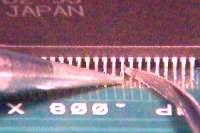
Procedure - Lead Lifting, Fine Pitch Gull Wing Components
Select the component lead that needs to be lifted. Apply a soldering iron and solder braid to remove the excess solder from the joint.
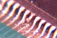
Gently place a pick behind the component lead to be lifted. Apply a soldering iron tip to the foot of the component lead. Apply slight force with the pick to lift the lead as the soldering iron reflows the joint. (See Figure 11)
Visually inspect or electrically test to ensure that the lead has been lifted. See (Figure 12)
If the lead needs to be reconnected, gently push the lead down until it touches the pad and solder.