The above video demonstrates tinning on SOIC type components. During this video demonstration, the solder pot shroud and nitrogen inerting was removed to clearly show the tinning process.
Outline
This procedure covers the robotic tinning of through-hole connectors.
Caution: Due to the need to completely control the rates of immersion and emersion of the through-hole connector pins and the dwell times in and between each process step, a robotic hot solder dip is recommended for through-hole connector tinning. Semi-automatic or purely manual solder dipping processes may not be capable of completely controlling the rates of immersion and emersion of the through-hole connector pins and only provide approximate dwell dipping times in the solder bath. Greater variation in the process may cause a higher chance of damage, including latent reliability problems.
Manual dipping required for full solder finish replacement is different than manual dipping currently practiced for meeting solderability requirements because of the increased need for 100% coverage on the through-hole connector pins to prevent whisker growth. Certain electronic component package styles may not lend themselves to robotic hot solder dipping and may require alternative processing.
Minimum Skill Level - Expert
Recommended for technicians with advanced soldering and component rework skills and extensive experience in most repair/rework procedures.
Conformance Level - High
This procedure most closely duplicates the physical characteristics of the original, and most probably complies with all the functional, environmental and serviceability factors.
Safety Glasses
Protect your eyes and your vision with proper safety glasses.
Solder Flux
Used to prepare solder surfaces and to prevent formation of oxides during soldering.
Wipes
Nonabrasive, low-linting wipes for cleanup.
Images and Figures
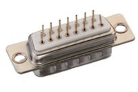
Through-Hole connector.
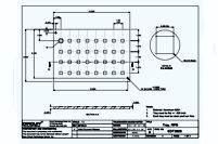
Figure 1. Custom holding fixture tray.
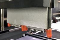
Figure 2. Robotic tinning system for controlled tinning of connector pins.
Figure 3. Connector pickup using grippers.
Figure 4. Application of flux to connector pins.
Figure 5. Connector pre-heat.
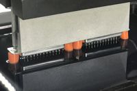
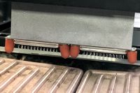
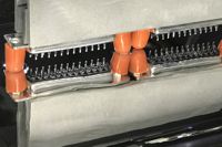
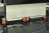
Figure 6. Connector immersion into molder solder wave.
Figure 7. Filtered hot water rinse.
Procedure
Ensure the connectors to be processed meet the requirements for acceptable Moisture Sensitivity Level (MSL).
Note: For information on baking and moisture level control, see 2.5 Baking and Preheating.
A matrix tray or custom holding fixture may be required. (Figure 1.)
Set up the Robotic Tinning System (Figure 2.) with the proper process parameters, including solder immersion depth, dwell times, insertion and extraction speeds, solder temperature, and other settings.
Note: Refer to the connector datasheet for guidelines regarding connector peak temperature specifications and other process parameters.
If needed, add protective covers or masking over protruding fasteners or other parts of the connectors that may become contaminated with solder.
Load the connector onto the fixture or matrix tray and place them into the Robotic Tinning System.
Activate the Robotic Tinning System's process cycle.
Using a paddle-type gripper, pick up one or more connectors from the tray. (Figure 3.)
Apply flux to the connector pins. (Figure 4.)
Remove the excess flux using the air knife.
Run the connector through the preheat stage to activate the flux and reduce the likelihood of temperature shock when placed in the liquidus solder. (Figure 5.)
Dip the connector pins into the solder until all the pins have been coated. (Figure 6.)
Run the connectors through a filtered hot water rinse to remove the flux residues. (Figure 7.)
Dry the connector using the air knife.
Return the tinned connector to its original position in the tray.
Wash the connectors in a cleaning system.
Dry the connectors in a general-purpose oven.
Visually inspect the connector's appearance, cleanliness, and condition. Check the pins for acceptable solder coverage and inspect the body of the connector for abnormalities.
Before packaging for shipping, dry the connectors again in a general-purpose oven at a temperature and for a time that meets the connector stated Moisture Sensitivity Level (MSL) requirement from the manufacturer's datasheet.
Evaluation
Visual examination.
Tests or other inspection criteria as specified by customer drawings.