The above video demonstrates tinning on SOIC type components. During this video demonstration, the solder pot shroud and nitrogen inerting was removed to clearly show the tinning process. For more information see 10.6.2 Tinning, QFP/PLCC Components, Robotic.
Outline
This procedure covers manual tinning of QFP and PLCC components.
Caution: Due to the need to completely control the rates of immersion and emersion of the QFP and PLCC component leads and the dwell times in and between each process step, a robotic hot solder dip is recommended for QFP and PLCC component tinning. Semi-automatic or purely manual solder dipping processes may not be capable of completely controlling the rates of immersion and emersion of the QFP and PLCC component leads and only provide approximate dwell dipping times in the solder bath. Greater variation in the process may cause a higher chance of damage, including latent reliability problems.
Manual dipping required for full solder finish replacement is different than manual dipping currently practiced for meeting solderability requirements because of the increased need for 100% coverage on the QFP and PLCC components leads to prevent whisker growth. Certain electronic component package styles may not lend themselves to robotic hot solder dipping and may require alternative processing.
Minimum Skill Level - Expert
Recommended for technicians with advanced soldering and component rework skills and extensive experience in most repair/rework procedures.
Conformance Level - Medium
This procedure may have some variance with the physical character of the original and most likely varies with some of the functional, environmental and serviceability factors.
Joint Industry Standard for Handling, Packing, Shipping and Use of Moisture/Reflow Sensitive Surface Mount Device
J-STD-001
Requirements for Soldered Electrical and Electronic Assemblies
J-STD-020
Moisture/Reflow Sensitivity Classification for Nonhermetic Surface Mount Devices
Manufacturer's Datasheets
Requirements for case temperature maximum and Moisture Sensitivity Level (MSL)
Additional Items and Supplies
Cleaning System
Batch or inline cleaning system for removing fluxes and contamination.
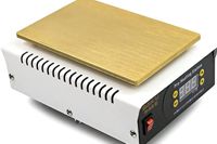
Hot Plate
Temperature adjustable heated plate to pre-heat components and circuit boards prior to tinning and reflow.
Microscope
Precision microscope with stand and lighting for work and inspection.
Oven
General purpose oven for drying, baking and curing epoxies.
Safety Glasses
Protect your eyes and your vision with proper safety glasses.
Solder Flux
Used to prepare solder surfaces and to prevent formation of oxides during soldering.
Solder Pot
Solder pot with static or dynamic solder wave for wire and electronic component tinning.
Tweezers
Multiple sizes and tip configurations of tweezers for various small parts handling needs.
Vacuum Pickup Tool
Manual or powered vacuum pickup tool for handling small parts and electrinic components.
Wipes
Nonabrasive, low-linting wipes for cleanup.
Images and Figures
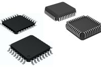
QFP and PLCC Components
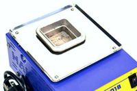
Figure 1. Solder pot.
Figure 2. Vacuum pickup tool.
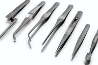
Figure 3. A variety of tweezers depending on the chip component size.
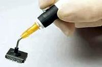
Figure 4. Hot plate used to preheat the components to reduce thermal shock.
Procedure
Ensure the QFP and PLCC components to be processed meet the requirements for acceptable Moisture Sensitivity Level (MSL). Note: For information on baking and moisture level control, see 2.5 Baking and Preheating.
Set up the Solder Pot with the proper process parameters, including solder temperature. (See Figure 1.) Note: Refer to the component datasheet for guidelines regarding component peak temperature specifications and other process parameters.
Turn on the Solder Pot and allow the temperature to stabilize. Test the wave to ensure the solder is flowing smoothly if a flowing wave is used.
Pick up a QFP or PLCC component using a vacuum pick-up tool or mechanical tweezer. (See Figures 2 and 3.)
Dip or apply flux to each lead of the QFP or PLCC component.
If needed, place the component on a hot plate. The heated plate will heat the QFP or PLCC component to activate the flux and evaporate volatiles. Pre-heating the QFP or PLCC component will also reduce the likelihood of temperature shock when placed in the liquidus solder. (See Figure 4.)
Dip each lead of the QFP or PLCC component into the molten solder. Follow recommended timing for immersion and emersion to properly tin the entire soldered surface areas.
Caution: Due to the need to completely control the rates of immersion and emersion of the QFP and PLCC component leads and the dwell times in and between each process step, a robotic hot solder dip is recommended for electronic component tinning. See caution note above.
If the flux used is water-soluble, run the components through a filtered hot water rinse to remove the flux residues. If the flux used is not water-soluble, use the appropriate flux remover solvent to clean the QFP or PLCC components.
Complete the cleaning by washing the QFP or PLCC components in a cleaning system.
Dry the QFP or PLCC components in a general-purpose oven.
Visually inspect the QFP or PLCC components' appearance, cleanliness, and condition. Check the QFP and PLCC component leads for acceptable solder coverage and inspect the body of the QFP and PLCC component for abnormalities.
Before packaging for shipping, dry the QFP and PLCC components again in a general-purpose oven at a temperature and for a time that meets the QFP and PLCC components stated Moisture Sensitivity Level (MSL) requirement from the manufacturer's datasheet.
Evaluation
Visual examination
Tests or other inspection criteria as specified by customer drawings.