X-Ray Finds Shorts in Drilled Holes
|
|
|
|
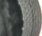
Figure 1: Layers in a .125" hole.
|
Drilling boards in the post-production environment is tricky work. Certainly, if the circuit board is populated with components and other hardware, the setup alone can be time-consuming. Additionally, datum points (the spots that ensure drilling precision) are not always easy to calibrate because these points are often designed for electronic versus mechanical location.
Things get dicey when the drilling occurs at a location where internal planes project into the newly drilled hole, especially when the planes are separated by 12, 10, 5, or even two-thousandths of an inch. And sometimes, there are a dozen or more planes stacked all the way through the height of the hole.
See the planes projecting into the hole in Figure 1. In these cases, the possibility of smear or the minutest conductive particle connecting the planes is high.

|
|
|
Figure 2: Enlarging a hole.
|
That's what inspection is for, to catch those potential problems, right? However, inspecting drilled holes using a microscope can be difficult. When the board is thick and large, maneuvering it to obtain a clear field of view covering the 360 degrees of the drilled hole is physically taxing and frustrating.
Proper backlight is crucial, and that light requires continual adjustment to keep the viewing area clear. The fact that the board is thick and the plane separation is minuscule demands a degree of optical magnification, which reduces the depth of view, further contributing to the challenge of ensuring a pristine cut surface.
|
|
|
Figure 3: One method of filling and strengthening a repaired hole.
|
There are many reasons a board may be drilled in post-production. Figures 2, 3, and 4 provide one view of how the drilling might be accomplished. In this case, it is to repair a damaged, non-plated hole.
The original drilling and inspection could be done perfectly, yet the epoxy sealing step might introduce or move suspect material to a location where it can cause electrical anomalies.
That can be problematic because optical inspection, as difficult as it already is, may no longer be able to see through the sealing material to the cut planes.
|
|
|
Figure 4: Hole drilled with insulating material separating hole from planes.
|
You may be thinking, "Why don't you just meter the board to see if any internal planes are shorting?" Great idea; it shows you know your business. Unfortunately, that information is not always available to the people doing the drilling, so they depend on using sharp cutters, stable drilling platforms, complete inspection, and clean environments to accomplish their tasks.
Recently, we received a board that indicated an anomaly at a drilled hole. The "shorts" were high resistance - in the kilo-ohm to meg-ohm range - but unwanted connections nonetheless. Visual inspection revealed nothing. How could we eliminate the short if we couldn't see it?
The solution was to use the oblique viewing capabilities of our Dage X-ray machine and peer through the board to get a clear view of the planes inside the drilled hole.
|
|
|
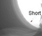
Figure 5: Short identified by oblique x-ray.
|
The Dage system was able to obliquely view the hole. Additionally, we were able to view the full perimeter of the hole. See Figure 5. Using this method, we were able to get a view of a ghostly fibrous piece or two that were likely causing the shorts, and therein, we had a place to focus our repair attention rather than blindly drilling and hoping to clear the problem.
The result was a success on the first attempt. I'm sure the oblique viewing technique is one we'll use again, and you may try it yourself if you're confronted with a similar situation.
Several members of the Circuit Technology Center team contributed to this feature story.
|
|
|
|
|