How to Fix Press-in Fastener Damage
|
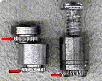
Press-in fasteners are a simple yet very important element of printed circuit assembly. As pictured in Figure 1, they are self-clinching fasteners that permit the mounting of heavy structures onto relatively thin circuit board substrates.
|
|
|
Figure 1: Typical press-in fasteners.
|
When inserted properly, and in the correct location, press-in fasteners provide an elegant solution to various chassis, heat sinks, stiffeners, and other hardware mounting demands.
The potential problem with press-in fasteners is in the nature of their mounting. The end with teeth, pictured in Figure 1, is fitted by force into a hole that is smaller than the teeth' circumference. That is what provides the grip of the fastener on the substrate. Forced insertion deforms the hole into which the press-in fastener is mounted, which is fine if that is what the hole was designed for, and in the vast majority of cases, that is exactly what happens.
However, in an industry that manufactures millions of assemblies a year, it is guaranteed there will be errors in manufacture and that some of them will have to do with improper press-in fastener insertion.
Unfortunately, a lot of crazy things can happen. For example, the wrong press-in fastener is inserted, the correct press-in fastener is inserted in the wrong hole, or the correct press-in fastener is inserted improperly. Any of these events can cause an unacceptable level of damage on an assembly.
|
|
|
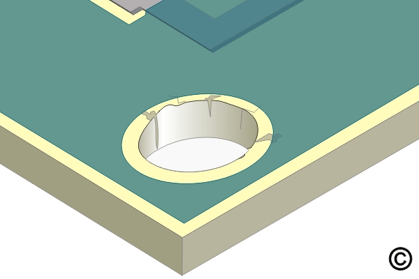
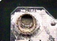
Figure 2: Base board damage at mounting hole location from improperly installed press-in fastener
|
At Circuit Technology Center, we see more than our fair share of these problems. In one case, a customer mistakenly inserted a press-in fastener in the wrong hole, see Figure 2. The guilty parties quickly realized their mistake and removed the press-in fasteners from the holes, but as you can see, the damage was already done.
The good news is, damage like this can be repaired. The alert customer sent the boards and Gerber files to Circuit Technology Center for evaluation. Our engineering staff evaluated the boards and determined there was no damage to internal circuitry or nearby power and ground planes which was confirmed by the customer's test data.
So the remaining challenge was to repair the laminate damage, mend the top to the bottom connection at the hole, and restore the board's appearance to an acceptable level.
What's the best way to do this? With all the technological advances in this industry, you may think that the "old-fashioned" eyelet is a thing of the past. But eyelets are still frequently used, and this is a perfect situation to use them. Here's how it's done.
The laminate damage is milled out with a precision micro-drill. The micro-drill is fitted with an appropriately sized ball mill, and using a microscope with proper lighting, a highly skilled technician removes the damage and flattens the raised surface.
|
|
|
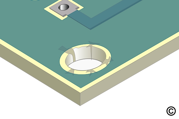
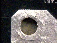
Figure 3: Completed repair of damage at the mounting hole.
|
An intermediate step of filling the location with matching material (perhaps an FR4 dowel) or filling with high-strength thermoset epoxy may be required.
Next, the hole is centered and drilled to the proper size using a high-speed precision drill system to insert an eyelet of the proper dimension.
This eyelet is "set" with a press designed specifically for this type of operation.
Finally, a technician, capable of skillfully soldering to heavy grounding surfaces, tins the eyelet and blends the flanges into the surrounding ground pad surface.
You are left with a repair that looks like the one pictured in Figure 3. Not a bad-looking repair!
Press-in fasteners can do some damage. If you are ever confronted by such a condition, give us a call, we just might be able to help you out.
Several members of the Circuit Technology Center team contributed to this feature story.
|
|
|
|
|